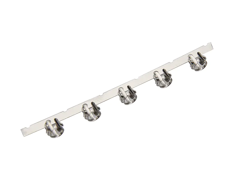
To the standard group member process of unity and die assembling quality control, the company with many years of production experience, developed a set of die set of specifications, the following with the wiring terminal mold group introduce the following.
Wiring terminals of the die set of nine made the following steps: 1, using micrometer measuring the thickness of the template, and promptly recorded in & lt;
Mould group set records & gt;
(
FIL-
059).
, the template of the thickness tolerance of plus or minus 0.
003 mm, when the mould is longer than the consists of two boards before and after the two pieces of plate thickness tolerance should be consistent, to avoid is a board that is tolerance, the other boards is negative tolerance, template thickness size out-of-tolerance or after deformation should be assistant general manager in a timely manner to reflect, completed by the mould tube chamber & lt;
Quality abnormal notice & gt;
And inform the supplier to processing.
2, template chamfering, Angle part of milling machine processing, the guide sleeve hole, the positioning pin Kong Xian chamfering after polishing, pay attention to the template line cutting casing mouth, lower die plate, mold base under the blanking hole do not allow the chamfering, chamfering sweeps clean, after the template with oil stone bulldozed.
Under 3, vice guide bush glue, template, stripper, plywood positioning pin hole, hole clean, roller bearing vice, positioning pin roller bearing clean, vice guide pin into the stripper first, three motherboards and backing plate with four dedicated dowel fixed together, locating pin with a small copper bar tapping can, of the gap between the template with 0.
01 mm gasket can't fit can guide bush glue.
Glue 8 hours rear can open the template.
Group 4, templates, check whether there is a need to put into the parts of the template, then use dowel pin under the fixed mold, locking check before three boards of blanking die hole, tapping hole, pin hole, screw holes, screw hole and whether there is leakage processing or offset, such as found that the problem solves promptly, the clearance between the three boards with 0.
01 mm gasket of plug, then lock the template, lock cross lock from inside to outside, two-thirds of the length of the screw to lock the template with are not beyond the template and advisable, technique in the same group of upper die.
5, lead column, guided sets of glue, the template is set up on the below template, with four long positioning PIN connection, confirm that the guide sleeve hole is swabbed clean after one by one to glue of guide bush, at the same time to the upper die parts to glue, glue PIN 8 hours rear can open the mold base.
6, the mould parts of set: group set to confirm before template box mouth wash clean, with chamfer parts after the first group of set mode, set in turn made stripper, plywood, stripper parts assembling complete back cover on the lower die, check the clearance between the template, is one by one, to check whether there is interference parts when clearance, and promptly eliminate, set to stand at the bending modulus of the plywood should be through the stripper, check whether the interference with the lower die, clearance is reasonable, confirmation before you load the splint.
Dowel PIN: 7, assembling all the height of the dowel PIN should be in tolerance of 0.
Within 005 mm, the punch after coated with oil, stripper for plywood, tight overall clearance when needed after the match, then lock stripper.
8, the overall mould check whether there is interference between upper and lower mould, four clearance Angle is less than 0.
015 mm, and record in the mould resume, if there is a gap, gap greater than zero.
015 mm, don't force hard mould clamping, should open the mould to check again after careful clamping, avoid damage to the parts.
After 9, clamping qualified, spring up and down mold base, check the lifting part and material in the mold within the guide plate is smooth.
Through the above nine steps, a wiring terminal mould has been completed group work.